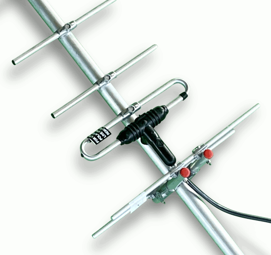


| Folded dipoles are commonly used in yagis intended for the telecommunications industry, often laid flat (coplanar) on the boom, seen in the two well known manufacturers examples! | ||
|---|---|---|
 |  |  |
The 'Driven Element' (DE) is probably the most important part of a yagi antenna. How it is constructed and the feedpoint protected is of critical importance! Seen above two commercial yagis manufactured by Messrs Jaybeam and Renair. Both have been leaders in the UK radio/telecommunications industry for several decades, their products have stood the test of time!
Here in the UK it is industry practice for the feedpoint to be enclosed in an overmoulding with a short flexible coax tail and female in-line N connector. Aerial riggers ascending very tall radio masts/towers prefer this scenario. Weatherproofing the feedline connectors is achieved by first wrapping with self-amalgamating tape and finally protected with Denso tape in order to prevent water ingress. The downside for Amateur Radio users is the difficulty in removal. My own method is to first wrap in plumbers PTFE tape which gets into all the contours. Finally wrap in a good quality UV stabilized PVC tape. When required this method is easy to remove but will last for decades!
It is best practice for the main feedline (usually Heliax type cable) to terminate onto a patch panel which should be well earthed.
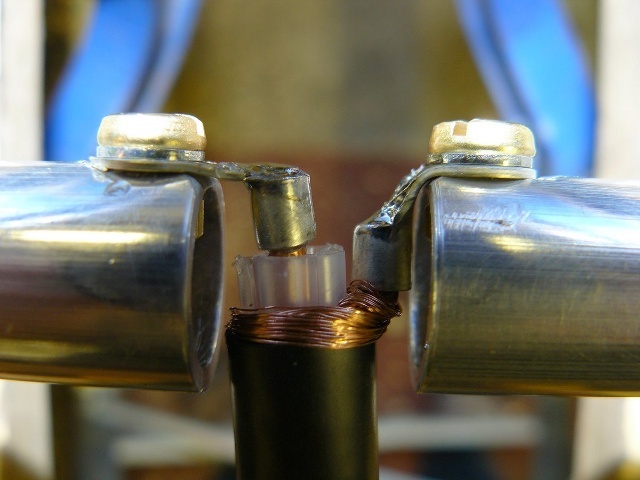
Connections to the DE must be kept very short, as seen in the right hand example above. At the higher frequencies stray inductance and capacitance from long lead lengths can become overwhelming and significantly alter resonance and matching characteristics. Not so critical on the HF bands.
Overmoulding machines and tooling are very costly, too expensive for most small amateur manufacturers. As a result enthusiasts tend to use open connections or modified plastic boxes. Unfortunately problems can occur with either of these solutions, for example the coax may not be supported properly!
Folded dipoles are commonly used in yagis intended for the telecommunications industry, often laid flat (coplanar) on the boom, seen in the two examples above. This practice has been in use for several decades by a whole host of manufacturers because it offers a simple way to effectively secure the folded dipole to the boom.
A requirement of many professional deployments is the presentation of a DC loop for continuity, monitoring and testing purposes particularly for firms in the security industry. A folded dipole offers this advantage, and also provides matching.
All CQM designs use a simple Split Dipole solution for ease of construction and avoid those limitations associated with NEC-2.
