


| Split Dipole | OWA Dipole | Folded Dipole |
|---|---|---|
 |  |  |
| LFA Loop | V Split Dipole |
|---|---|
 |  |
G4CQM's forensic investigation Dipoles Explored puts paid to myths propagated on the Internet concerning the pros and cons of particular dipoles and their use as yagi driven elements!
To create a level playing field the following analysis has been carried out in K6STI's Antenna Optimizer Professional (AOP) version software. AOP is perfect for analysis of loops and bent elements because it includes a special correction for this problem that works without altering segmentation or increasing computation time.
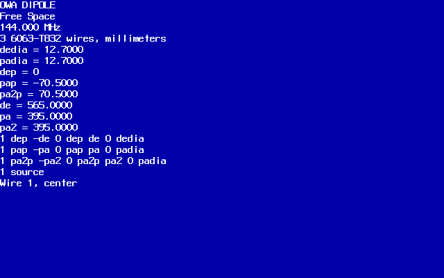
Each dipole has been tuned for minimum reactance at 144MHz. Segmentation has been set at 25 segments per λ/2 in all examples. Finally, all of the Dipoles Explored uses 1/2 Inch (12.7mm) OD tubing.
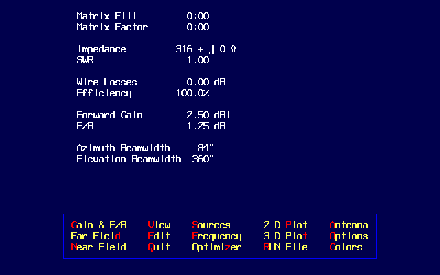
The Split Dipole, Folded Dipole and LFA Loop all exhibit their own respective intrinsic impedance...
Meanwhile the V Split Dipole can easily be adjusted to 50Ω by simply changing the swept back angle and tuning out reactance by altering length!
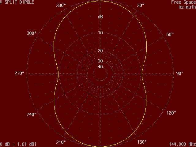
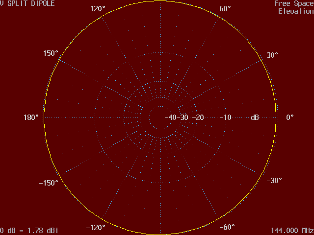
Note that the LFA Loop and V Split Dipole exhibit some pattern distortion (not symmetrical) which has an impact on the final overall pattern when located in a yagi build, LFA Loop being worst of all!
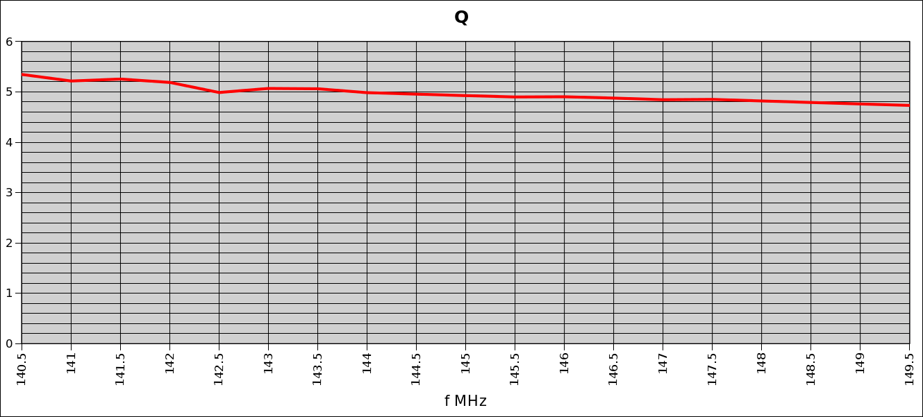
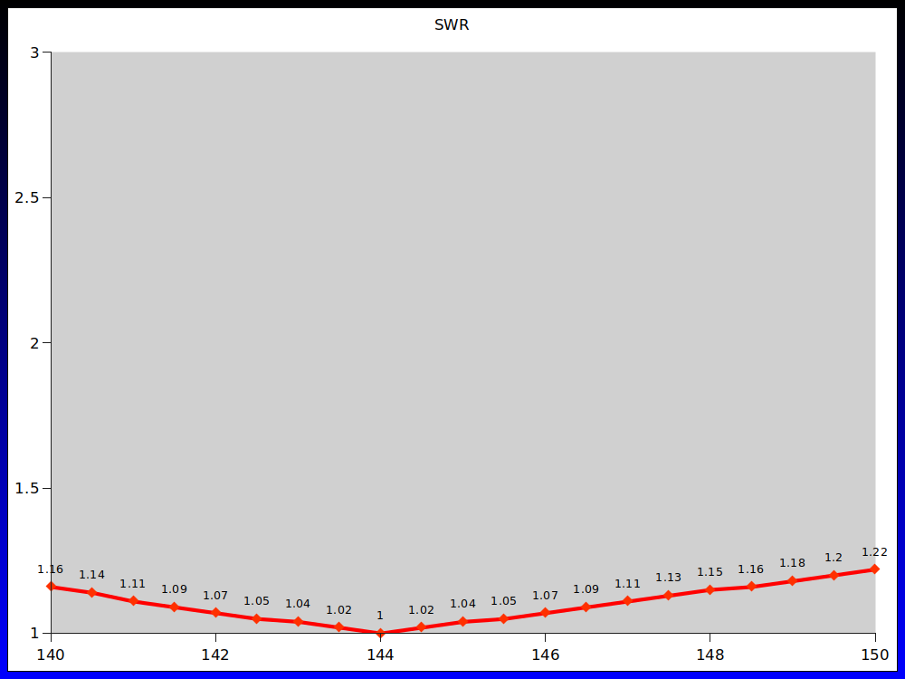
It is interesting to see that in itself the V Split Dipole doesn't improve operational bandwidth, indeed has the highest average Q-factor of all the Dipoles Explored. Conversely the OWA Dipole benefits from the lowest average Q-factor of all the Dipoles Explored and also raises the feed-point impedance, very useful when incorporating into a yagi build!
Integration and the working of each of these different dipole types into a yagi build is complex. Mutual coupling occurring between elements and subsequent loading effects will impact on resultant intrinsic feed impedance in a positive or negative way! This is dependent on the tuning regime of all the parasitic elements along with the driven element which also determine the polar pattern in both E & H planes, and over the desired operational bandwidth.
Radio Amateurs may be seduced by marketing speak into the benefits of a particular system. However, the reality is that all of the different feed systems are in one way or another a compromise, no one system is perfect, so don't be taken in by boastful claims!
For many Ham Radio enthusiasts ease of construction may well be the key deciding factor! To see how an OWA Dipole can be used in a yagi build go to AOWA (Advanced OWA) by Derek Hilleard G4CQM
Click on images for full size view, opens in new window!
| Split Dipole |
|---|
 |
| Split Dipole in AOP | Antenna File - Symbolic Dimensions |
|---|---|
 |  |
| Azimuth | Elevation |
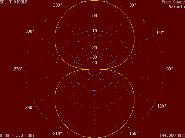 |  |
| Split Dipole - Average Q-factor = 4.9 (140-150MHz) |
|---|
 |
| Split Dipole - SWR |
|---|
 |
Click on images for full size view, opens in new window!
| OWA Dipole |
|---|
 |
| OWA Dipole in AOP | Antenna File - Symbolic Dimensions |
|---|---|
 |  |
| Azimuth | Elevation |
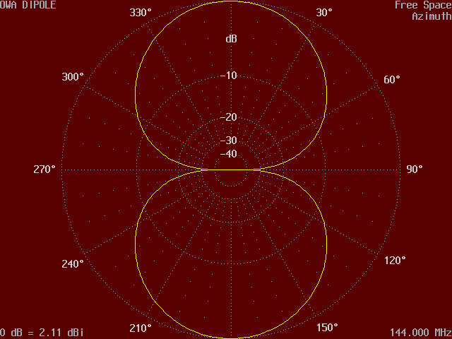 | 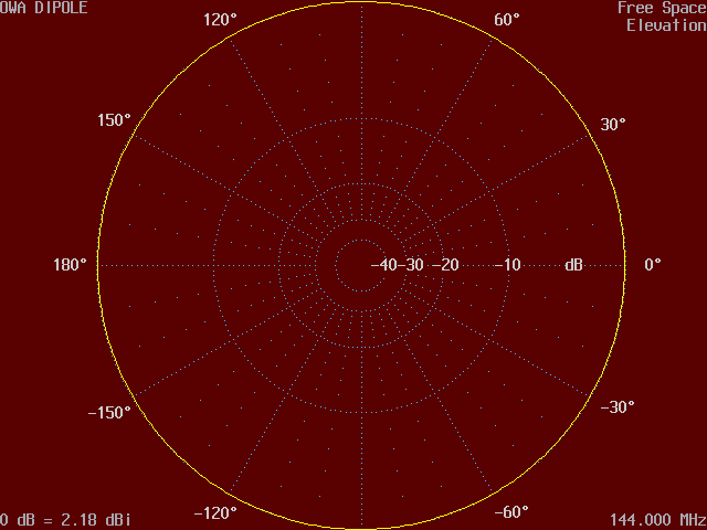 |
| OWA Dipole - Average Q-factor = <1 (140-150MHz) |
|---|
 |
| OWA Dipole - SWR |
|---|
 |
Click on images for full size view, opens in new window!
| Folded Dipole |
|---|
 |
| Folded Dipole in AOP | Antenna File - Symbolic Dimensions |
|---|---|
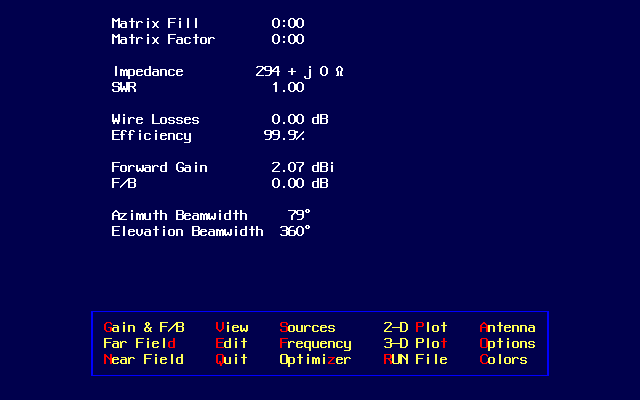 | 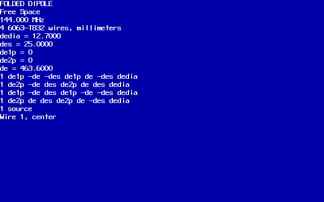 |
| Azimuth | Elevation |
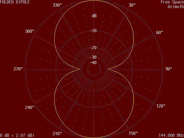 |  |
| Folded Dipole - Average Q-factor = 3.2 (140-150MHz) |
|---|
 |
| Folded Dipole - SWR |
|---|
 |
Click on images for full size view, opens in new window!
| LFA Loop |
|---|
 |
| LFA Loop in AOP | Antenna File - Symbolic Dimensions |
|---|---|
 |  |
| Azimuth | Elevation |
 |  |
| LFA Loop - Average Q-factor = 2.5 (140-150MHz) |
|---|
 |
| LFA Loop - SWR |
|---|
 |
Click on images for full size view, opens in new window!
| V Split Dipole |
|---|
 |
| V Split Dipole in AOP | Antenna File - Symbolic Dimensions |
|---|---|
 |  |
| Azimuth | Elevation |
 |  |
| V Split Dipole - Average Q-factor = 7.1 (140-150MHz) |
|---|
 |
| V Split Dipole - SWR |
|---|
 |
| G4CQM 50Ω Coaxial Dipole - Original Drawing |
|---|
 |
The G4CQM 50Ω Coaxial Dipole was first conceived and tested during the month of January in 1994. It is in fact a conventional Split Dipole with just one difference. There is a centre wire conductor (insulated) running through the internal bore which terminates at either end. It was intended as a drop in replacement used in 50Ω Direct Feed yagi antennas designed and manufactured by PowAbeam Antennas. It doesn't in itself provide matching, this occurs as a consequence of the combined interreaction of all the elements (parasitics and driven)!
It was also adopted in 1999 by Communication Aerials Ltd of Westbury Witshire as a replacement driven element for their new range of yagi antennas. A requirement of many professional deployments is the presentation of a DC loop for continuity, monitoring and testing purposes particularly for firms in the security industry. The centre wire conductor provides for this need!
Coaxial dipoles aren't new, over the decades there have been numerous implementations, and a range of performance claims. Their modus operandi has often confounded the so called experts!
| Basic Circuit |
|---|
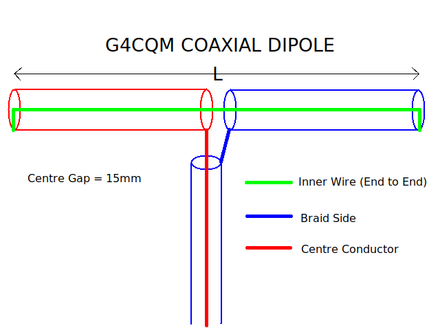 |
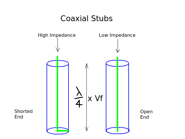
At VHF frequencies RF currents flow on the outer surface of conductors (skin effect). External surfaces of the G4CQM 50Ω Coaxial Dipole carry the flow and distribute RF current in exactly the same way as a Split Dipole, there is no difference. However, the wire inside the bore terminating at either end creates two shorted end λ/4 coaxial stubs opposing one another, as a result no RF current flows on this wire! From a DC current point of view this wire provides a loop for continuity, monitoring and testing purposes. In commercial application feeder cables usually terminate on a bulkhead patch panel which is grounded. So, the G4CQM 50Ω Coaxial Dipole enables static charges to harmlessly discharge through the internal wire and then to earth. Meanwhile nearby lightning strikes that induce currents on the dipole structure are prevented from reaching destructive transient voltages because they are shorted and discharge to safely to earth!
When the G4CQM 50Ω Coaxial Dipole is used in conjunction with a suitable slip on or clip over ferrite placed close up to the feedpoint or alternatively the 'λ/4 Half-Loop Trick' then no 'Balun' is required.
| Coaxial Stubs |
|---|
 |
