| Optimized Wideband Antenna - 2M Band OWA Dipole |
|---|
 |
Author G4CQM 02-06-2021
This page is intended to give readers an insight into the history and development of G4CQM's Advanced OWA (AOWA) style yagi designs.
Designing High Performance yagis for Amateur Radio isn't as easy as you might first think. There are many variables and an almost infinite number of permutations of element position, length, and diameter. Each set of build dimensions gives rise to a completely different design. Some designs however are much better than others!
In recent years the quest for novel/gimmick driven elements has become an obsession with some but are there any real and tangible advantages on offer? Decide for yourself and look at Dipoles Explored by G4CQM.
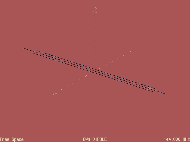
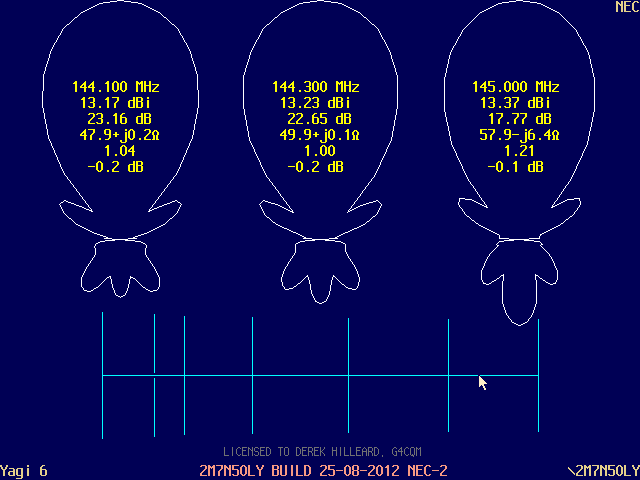
The OWA (Optimized Wideband Antenna) is an antenna employing a feed-point matching system conceived by Professor Jim Breakall, WA3FET (Penn State University), and delivers an increase in feed-point impedance whilst substantially improving on the available/useable VSWR bandwidth. Above is a 2M Band OWA Dipole example based on Jim's original 80M implementation, and configured in K6STI's AOP (professional version) software. Antenna file (.ANT) using Symbolic Dimensions can be seen here... OWADIPOLE.ANT.txt
Raising feed-point impedance is particularly useful in yagi design where mutual coupling and loading effects can drop feed-point impedance to very low values, and then become difficult to match whilst also incurring greater losses.
Note that to more accurately simulate the original OWA antenna concept, the 144MHz version requires wires (elements) of only 0.5mm diameter in proportion to the increase in frequency and shorter wavelength. Flanking the Split Dipole (the driven element) there are two shorter parasitic elements spaced some 0.01λ from the driven element, without this configuration the resultant polar pattern becomes distorted (not symmetrical). Those familiar with yagi design will see these parasitic elements in the same context as the yagis first director (D1) which enhances gain in the forward direction.
In realized OWA yagi designs only one parasitic element is required because some forward gain is of help and no hindrance, suggested spacing distance of around 0.05λ is required. However, with large diameter elements this spacing has to be increased accordingly.
Looking across the Internet it is clear that some online experts haven't understood what a real OWA yagi should look like, some designs can be made wideband without close spacing between the driven element and first director! An example of this method would be my own 2M7N50LY design type which can be seen further on.
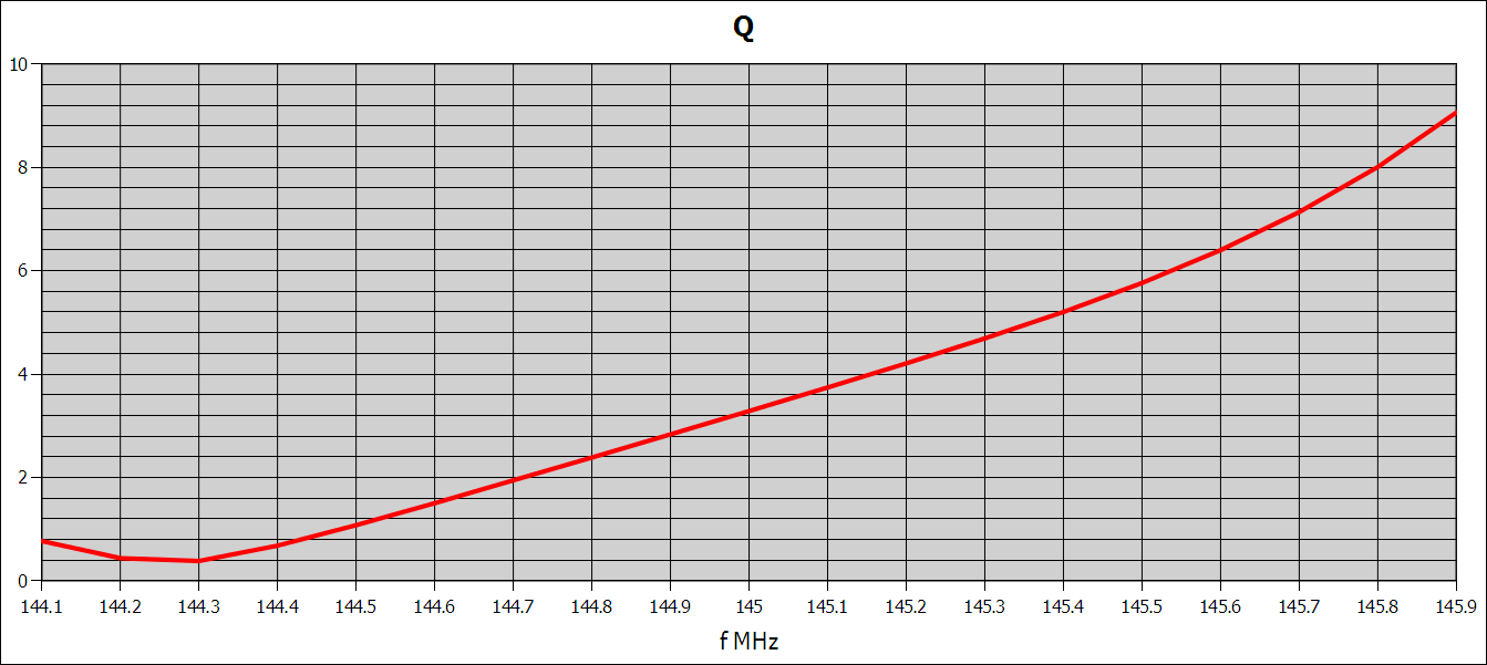
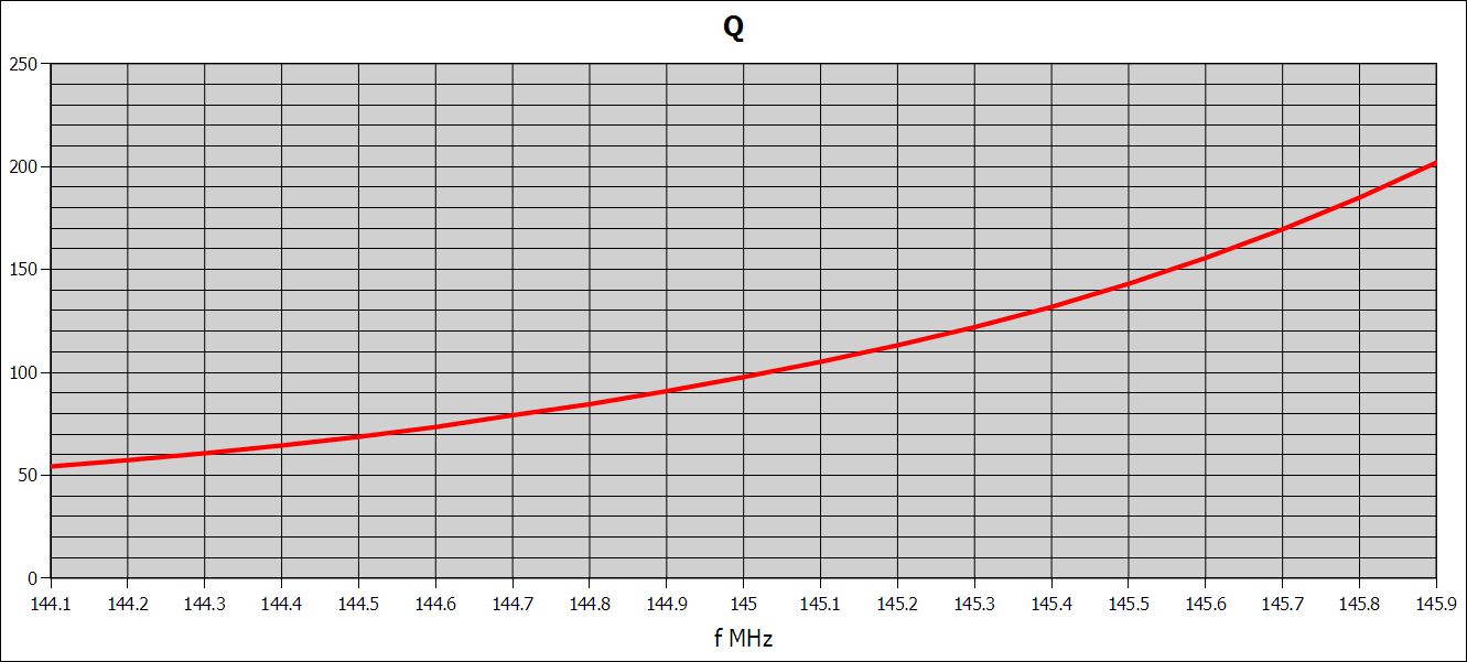
The OWA Dipole is truly remarkable, an example below simply demonstrates that an increase in impedance is possible whilst also significantly lowering the average Q-factor, with notable improvement in operational bandwidth!
Early in 1994 my research and experiments focused on choosing a suitable yagi design for the 2M Band, with particular attention paid to the driven element type. From a commercial point of view ease of construction and repeatability were of paramount importance!
After trying/testing a Hairpin Match detailed in the ARRL VHF/UHF handbook and encountering build problems along with poor/inconsistent results, it was time for something different (hairpins are highly reactive located right on the feed-point and so tiny variations in construction give rise to volatility)! It was then that I decided to test the concept of Direct Feed and simple Split Dipole driven element. This idea was just starting to become popular and adopted by others.
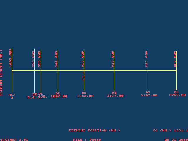
To begin with I opted for YAGIMAX by the late Lew Gordon (K4VX) to design the first PowAbeam Antennas 2M0818SK 8 element 2M Band yagi. Software by Lew is very easy to use and true enough delivered a stable and reliable design. However, YAGIMAX is somewhat limited optimizing for gain and F/B only, and without being able to control the front/rear region. Despite these limitations 2M0818SK has a remarkably flat frequency response. Note the OWA style close spacing between the Split Dipole driven element and D1.
| PowAbeam Antennas 2M0818SK 8 element 2M Band yagi seen in YAGIMAX |
|---|
 |
 |
The original G4CQM PowAbeam 8 element yagi (2M0818SK) certainly qualifies as an OWA style yagi. However, compare overall performance with modern WA9XX AOWA (lower temperature and better G/Ta in a noisy residential environment simulation) and you will see the difference!
| Animation showing K6STI's YO7 Professional screen options |
|---|
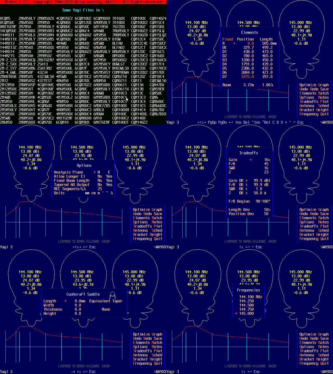 |
A few years later around 1999/2000 I decided to purchase K6STI's YO7 and AO Pro version software for my work as a consultant at Communication Aerials Ltd of Westbury Wiltshire. This enabled me to refine, verify and calibrate my commercial yagi designs against the Numerical Electromagnetics Code (NEC).
YO analyzes and optimizes Yagi-Uda antenna designs on your PC. It runs hundreds of times faster than NEC- or MININEC- based antenna-analysis programs. YO's mathematical model is more complex than the W2PV Yagi model, simpler than MININEC, and more accurate than either. YO models tapered elements, mounting brackets, the boom, matching networks, dual driven elements, and conductor loss. YO represents antennas in free space or over ground. It can model two identical Yagis stacked in the H-plane in free space. YO calculates mutual-impedance interactions for all of these cases. It also can ignore Yagi-to-Yagi interaction and model large rectangular arrays of Yagis.
YO uses a conjugate-gradient optimizer that combines the Fletcher-Reeves and Polak-Ribiere methods.
You can invoke NEC from within YO by pressing the spacebar to verify results, look for NEC top right hand corner, from experience the very best designs occur when YO and NEC agree
YO7 Notes
To reduce screen clutter, YO7 doesn't label the figures displayed within the Yagi patterns. They are as follows:
1. Frequency
2. Forward Gain
3. Front-to-Rear Ratio
4. Input Impedance
5. Standing-Wave Ratio
6. Elevation Angle or Gain FOM
YO displays elevation angle for Yagis over ground and gain figure-of-merit for single-Yagi, free-space models.
YO defaults to a generalized definition of front-to-back ratio.
The notation 12.7-j15.4 means a resistance of 12.7 ohms in series with a reactance of -15.4 ohms.
Z stands for impedance.
The lambda symbol (λ) means wavelengths.
YO uses a generalized notion of standard front-to-back power ratio to characterize pattern quality. Conventional F/B is the ratio of forward power (at 0 degrees) to that radiated in the opposite direction (at 180 degrees).
YO's generalized F/B is the ratio of forward power to that radiated within a specified region to the rear of the antenna. This is called front-to-rear ratio (F/R).
Yagi designs maximizing conventional F/B often have large backlobes at angles other than 180 degrees. Much better patterns result when you optimize a Yagi for F/R.
The F/R region begins at 180 degrees and extends forward to a specified angle (90 degrees by default).
| Original G4CQM PowAbeam 8 element yagi refined in K6STI's YO7 Pro | |
|---|---|
 | |
| 2M0818SK OWA style very low average Q-factor | |
 | |
| E-Plane | H-Plane |
 |  |
| Residential performance - Four yagis with DL6WU stacking distances | |
 | |
DJ9BV designs soon became popular in the mid to late 90's, and they did perform very well. These designs employed a low element boom density/wide spacing. Some of my own best DX was worked with the BVO2-3WL 50Ω direct feed design! However, there was a problem, they were sensitive to their surroundings and detuned in wet weather... Several Radio Amateurs have provided feedback regarding this problem. The reason: Because these designs had a very high average Q-factor, and high levels of reactance at the HF end of the band. In short, they were gain optimized yagis. BVO2 designs had a unique current distribution profile, I tried to mimic this in the PowAbeam Antennas designs at that time.
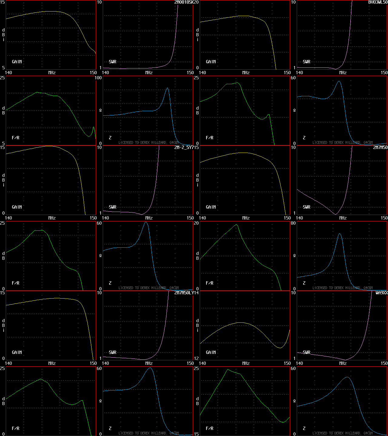
When I returned to designing yagis for Ham Radio in 2008 things had moved on! The first of my so called new designs were still based on the gain optimized concept as seen in the 2M7N50 design below... Meanwhile, Pop YU7EF had established a range of unique 50Ω low noise designs that had a lower average Q-factor than the DJ9BV designs. As a result Pop's designs were more stable and had gained considerable favour.
I soon discovered some new techniques (not OWA style) to design low Q long yagis as seen below in the 2M7N50LY example, the boom length is slightly longer and position of the Split Dipole driven element and D1 has changed, still wide spacing throughout. Note the much lower average Q-factor and improved F/R power ratio too.
| G4CQM 2M7N50 gain optimized design |
|---|
 |
 |
| G4CQM 2M7N50LY low average Q-factor design with improved F/R |
|---|
 |
 |
During the early months of 2013 I decided to fully embrace 50Ω Direct Feed - Low Q - Low Noise - OWA style... An excellent example of what defines an Advanced OWA (AOWA) design can be seen below in Wave Antennas WA9XX... It has very close spacing between the Split Dipole driven element and D1, OWA style. Meanwhile the parasitic elements are spaced in a specially contrived sequence in order to deliver a tight/clean pattern in both E and H Planes. In the words of Pop YU7EF, this yagi design has carefully balanced parameters!
In conclusion my research reveals that designing for maximum forward gain does not necessarily deliver the best G/T (strictly G/Ta) and Advanced OWA (AOWA) yagi designs having six or more elements in total are more than capable of outperforming those yagi designs employing novel/gimmick driven elements. The critical part is getting the Split Dipole driven element and D1 spacing just right in relation to the other elements, so delivering the real Optimized Wideband Antenna (OWA) benefits.
| Animation showing 140-150MHz bandwidth evolution of the AOWA |
|---|
 |
| WA9XX.nec |
| 4WA9XX.nec |
| 4WA9XX.zip |
