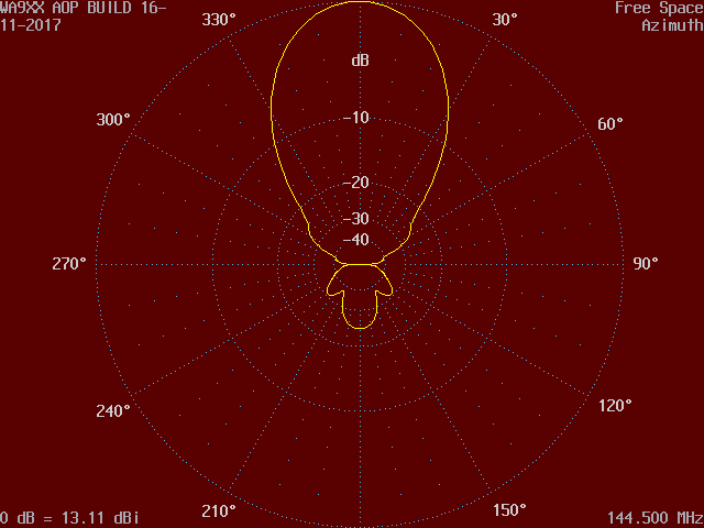
Click on images for full size view including azimuth and elevation animations.


| Comparing G0KSC's 8 element LFA with CQM WA9XX OWA, same boom length Click on images for full size view including azimuth and elevation animations. | |
|---|---|
 |  |
 |  |
 |  |
 |  |
01-02-2025... Antenna design is often considered to be a 'black art', and when something apparently new arrives it draws attention... Back around 2010 a somewhat different looking yagi type antenna hit the bands. With a stretched loop driven element laid flat on the boom, G0KSC's LFA had arrived!
In reality however coplanar driven elements such as folded dipoles mounted flat on the boom were not new. As previously discussed in article Driven Element both commercial designs Jaybeam and Renair yagis are good examples, there are many others to be found across the radio/telecommunications industry.
Folded dipoles deliver impedance transformation, a ratio of 1:4... In essence the LFA loop style driven element is also a 1:4 transformer and so raises the yagis intrinsic impedance of 12.5 Ohms to that of 50 Ohms, enabling direct feed connection.
In the case of a simple direct feed split dipole driven element, perhaps fed through a balun has no need for a matching network. Whilst convenient, yagis optimized for direct 50 Ohms feed have in the past performed less well than matched, low-impedance designs. However, utilizing new and advanced computer assisted techniques designs such as WA9XX has finally narrowed this performance gap! This has been accomplished by adopting the OWA principle (close spaced DE and D1) and unique/unconventional spacings and lengths within the director chain.
Meanwhile G0KSC had suggested that his antenna would not show the true SWR in any antenna modelling package unless using one with the latest NEC-4 calculation engine installed. Infact this is not so... As an example K6STI's Antenna Optimizer Professional (AOP) version software is perfect for analysis of loops and bent elements because it includes a special correction for this problem that works without altering segmentation or increasing computation time.
At the time there was mention that the LFA had been optimized with electromagnetic simulation software FEKO (since acquired by Altair) taking advantage of its particle swarm optimizer. The azimuth plot certainly looked different, however close scruntity suggests some unusual pattern distortion/interference is present. When running a frequency sweep (144 - 145MHz) this pattern instability is visible with the 8 element LFA when compared to the WA9XX OWA, as seen above in the azimuth and elevation animations.
Some yagi designs are better in stacking configurations than others, a clever designer can exploit this fact, particularly when it comes to ranking in the VE7BQH Antenna Tables!
A simplified example of the tables (similar style) is seen below in which WA9XX has lowest temperature and best G/Ta of those yagi antennas listed.
Frankly you don't need elaborate driven elements to see great patterns. From a construction point of view loops or bent elements are more difficult to fabricate, and commercially more expensive to manufacture!
Antenna files: 8LFA.ANT and WA9XX.ANT
References:
| ~ DL6WU OR * Designers stacking | T_sky = 290K whilst T_earth = 5400K (Residential Environment) | ||||||||||
|---|---|---|---|---|---|---|---|---|---|---|---|
| 1 YAGI | < 4 YAGIS > | ||||||||||
| Design ID | λ | Boom (m) | BW Az° | BW El° | Gain (dBi) | F/B (dB) | Ga (dBi) | Ta (K) | Ant G/T (dB) | DE | Q-factor Avg 144-146 |
| ~GTV28W | 1.78 | 3.696 | 40 | 48 | 13.36 | 27.7 | 19.25 | 504.0 | -7.77 | V Split Dipole | 17.75 |
| *WA9XX | 1.79 | 3.725 | 42 | 48 | 13.13 | 24.8 | 18.74 | 386.0 | -7.13 | Split Dipole | 19.75 |
| *8LFA | 1.79 | 3.729 | 42 | 48 | 13.18 | 25.5 | 19.02 | 468.1 | -7.68 | LFA Loop | 21.14 |
